01 / VISUAL INPUT2D

A shape in pixels.
The image shows an outline. Depth and unseen surfaces remain to be interpreted.
Image-to-3D / project 04
An AI workflow that turns 2D images into 3D geometry and STL files, connecting a visual idea with a model you can inspect and take into a fabrication workflow.
The image shows an outline. Depth and unseen surfaces remain to be interpreted.
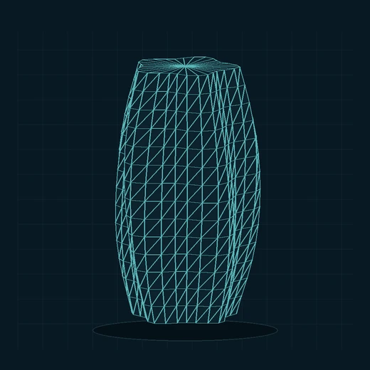
A mesh describes the form in three dimensions, ready to inspect from different angles.
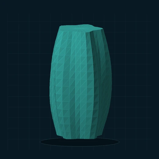
Rotation reveals the depth and surfaces a single image cannot show.
Illustrative sequence: these three views use one procedurally created sample shape. They explain the image-to-3D idea and are not a recorded Adam conversion. The downloadable STL matches this sample.
A 2D picture contains visual cues, but it does not specify every surface or dimension. Adam explores that translation: generating a three-dimensional interpretation and producing an STL for the next stage of the workflow.
Conceptual workflow
Choose a view that communicates the subject’s shape and separates it clearly from the background.
Use image-to-3D inference to create a proposed surface, including depth not directly specified by the picture.
Inspect the silhouette, unseen sides and fine features. Compare the interpretation with the intended object.
Carry the shape into STL format for downstream inspection, preparation and possible fabrication.
Capability-level view of the project. Review steps describe how to assess the result; they do not imply automated mesh repair or guaranteed print readiness.
The AI contribution
The image provides visual evidence. Generating a 3D object requires an interpretation of depth, volume and hidden surfaces.
That makes output review part of the process: a convincing front view can still hide an unexpected back, thin feature or distorted proportion.
A clear silhouette and readable subject make the intended form easier to communicate. Occlusion, busy backgrounds and ambiguous shapes leave more for the model to infer.
Turning the model reveals surfaces that were invisible in the input. Review the whole form, not just the view that resembles the source image.
STL represents a surface as triangles. It does not carry the source photograph, image textures or an inherent physical unit. Scale and material choices belong to the downstream workflow.
Skills behind the project

Working with images as the starting point for a geometry-generation task and understanding how the visual input shapes the result.

Connecting image input, 3D generation and output handling into a coherent image-to-model process.

Evaluating the generated shape in three dimensions and identifying where the result needs a closer look.

Making the relationship between source image, inferred shape and exported file understandable to the person using the workflow.
This case study describes Adam at the workflow level. Model names, infrastructure details and measured conversion results are not asserted here.
From export to fabrication
Review proportions, unwanted fragments, holes and intersecting surfaces before treating the mesh as finished.
Set intended dimensions and assess thin features. The same geometry may behave differently at different print sizes.
Check the model in the intended slicer, considering support needs and the constraints of the printer and material.
These are downstream review considerations, not claims that Adam automatically performs each check or guarantees a printable result.
Explore the illustration
The animation, wireframe and flat silhouette all refer to the same original demonstration geometry. The matching STL is included so you can inspect the form in a compatible 3D tool.
This is a small procedural example made for the portfolio artwork. It is not an Adam-generated production result.
Illustrative sample / original geometry
STL is unitless. Choose scale intentionally in your 3D tool. The sample has basic closed-surface checks; it has not been certified for printing.